
Concrete Pump Structural & Hydraulic Troubleshooting: Real-World Case Studies
Master concrete pump maintenance with three professional engineering case studies. Learn actionable repair methods for boom cracks, outrigger failure, and hydraulic cylinder drift.

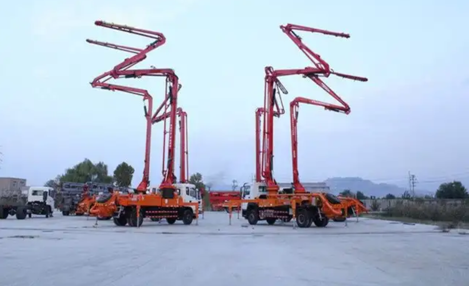
As a concrete pump truck service engineer with over a decade of hands-on field experience, I can tell you that these specialized machines are the absolute lifelines of modern construction sites. With their multi-sectional, highly maneuverable placing booms, they offer unparalleled flexibility and efficiency in pouring concrete.
However, because these machines operate under high pressures and cyclic, dynamic loads, structural and hydraulic failures are inevitable if proper maintenance is neglected.
To help fleet managers, operators, and mechanics keep their equipment running safely and efficiently, I have compiled three critical, real-world troubleshooting case studies detailing structural fatigue, structural tearing, and hydraulic drifting.

Case Study 1: Concrete Pump Placing Boom Cracking (Fatigue Failure)
Concrete pump placing booms are high-strength steel box structures. While high-strength steel offers an excellent strength-to-weight ratio, it features a higher carbon equivalent. This makes the parent metal prone to poor weld penetration during manufacturing, rendering it susceptible to fatigue cracking under cyclic loading.
During pumping, the concrete cylinders cycle alternately, generating periodic alternating stresses that accelerate fatigue. Boom cracking is one of the most common challenges faced by manufacturers and fleet owners alike.
1. The On-Site Failure Phenonmenon
During a routine inspection of a multi-section boom, severe cracking was identified on the Boom 3 head joint:
- The weld joint between the upper cover plate and the connecting shaft sleeve had cracked (rust markings indicated this was a long-standing, pre-existing fatigue crack).
- The crack had propagated transversely into the end side plate, causing structural cracking in the parent metal of the side plate.
- No cracks were found at the junction of the connecting shaft sleeve and the lower cover plate.
- Upon disassembling Boom 3, we discovered abnormal, uneven wear on the connecting pin and bronze bushing between Boom 2 and Boom 3.
This level of damage compromised the structural integrity of the entire boom template, rendering the machine unsafe to operate without a complete overhaul or replacing Boom 3.

2. Root Cause Analysis
This is a classic fatigue crack triggered by a combination of geometric, metallurgical, and wear factors:

- Geometric Stress Concentration: This pump truck utilizes an R-fold boom configuration. To lower the overall center of gravity when folded, Boom 3 is engineered with a pre-bent profile. When fully extended as a cantilever beam, this geometry generates a severe additional torsional stress concentrated at the boom head. Under horizontal working conditions, the maximum tensile stress on the end side plate (above the connecting sleeve) reached 439 MPa. Furthermore, the $135^\circ$ angle between the upper cover plate and the sleeve tangent formed a sharp geometric transition point, generating high localized stress concentration under cyclic loading.
- Metallurgical & Welding Incompatibility: The boom plates are made of high-strength steel, whereas the shaft sleeve is made of Medium Carbon Steel (Grade 35). Welding these two materials together requires extremely strict process controls. If improperly welded, the weld metal absorbs excessive carbon from the Grade 35 steel, resulting in a brittle, low-ductility weld seam that easily acts as a crack initiation site under stress.
- Mechanical Wear: Severe wear and misalignment of the Boom 2/3 pin and bronze bushing exerted heavy eccentric loads on the joint, compounding the localized stress.
3. Engineering Redesign & Repair Solution
To resolve this issue permanently, we implemented a structured design modification alongside a rigorous welding procedure:
- Redesigning the Upper Cover Plate: We extended the upper cover plate and reshaped it into a smooth arc parallel to the tangent of the connecting sleeve. This eliminated the $135^\circ$ sharp transition point. Consequently, the tensile stress at the weld toe dropped to 120 MPa, and the maximum tensile stress on the end side plate decreased to 325 MPa.

- Upgrading Shaft Sleeve Metallurgy: We replaced the Grade 35 steel sleeve with Q345A steel. This low-alloy steel features superior weldability with high-strength plates, significantly improving the impact toughness of the weld joint.
- Adding a Top Reinforcement Plate: Because the top plate of the Boom 3 head primarily experiences tensile stresses, adding a structural reinforcement plate over the repaired butt joint provides an extra margin of safety.

⚠️ Critical Welding & Repair Instructions
- Preparation by Cold Working: Gouge out and remove the damaged end side plate, arc plate, sealing plate, lower cover plate, and shaft sleeve. Ensure the cutting line is at least 5 mm away from the final weld prep area. The remaining stock must be removed via mechanical grinding or machining (cold working) to prep the weld bevels, preventing thermal micro-cracking in the parent metal.
- Fit-Up Inspection: Reassemble the new boom head components and sleeve precisely to blueprint specifications, keeping assembly tolerances tight and uniform.
- Rigid Fixturing: Clamp and fixture the boom assembly rigidly to a welding jig to prevent severe distortion during the welding process.
- Preheating & Thermal Control: Clean the weld zone until it exhibits a bright metallic luster. Preheat the assembly and maintain an interpass temperature compliant with high-strength steel standards. Use gas metal arc welding (GMAW) with multi-pass, low-heat input techniques. Perform post-weld heat treatment (PWHT) to relieve residual stresses.
- Final Machining: Use a portable line-boring machine to finish-bore the sleeve to meet exact assembly tolerances, and install a brand-new pin and bronze bushing.
Case Study 2: Outrigger Box Tearing (Severe Structural Instability)
During a high-rise pour, a foreign-brand concrete pump was operating with all front and rear outriggers fully extended. When the placing boom was swung to the front-right quadrant at its maximum horizontal reach, the root of the right-front outrigger telescopic box tore open.

The bottom plate at the root and its underlying box structure detached entirely, causing the right-front outrigger to slip outward. The horizontal extension cylinder snapped instantly, leading to a complete loss of structural stability and a catastrophic rollover accident.
1. The Outrigger Structural Layout
This pump truck utilizes an X-type outrigger layout. The front outriggers feature a two-stage telescopic structure where the inner legs slide inside the outrigger boxes of the lower chassis. The rear outriggers swing out via pivot pins.
To withstand the heavy torsional forces from the boom turntable, the undercarriage features a subframe connected to the truck chassis. The outrigger box consists of vertical side plates, a bottom plate, and an underlying reinforced box structure designed to distribute the bending moments.

2. Root Cause Analysis
- Neglecting Micro-Cracks: Inspection of the fractured surfaces showed heavy oxidation and rust. This proves the weld joint between the outrigger box and the chassis had been cracking gradually over a long period. This was a progressive fatigue failure that went unnoticed during daily inspections.

- Severe Weld Defects: Microscopic and visual inspections of the unfailed sections showed poor weld profile consistency and extensive cold laps (lack of fusion). Strikingly, the reinforcement plates were completely unwelded (skipped welds) around their boundaries, preventing them from carrying any structural load.
- Poor Stress Path & Bending Moments: Due to deformation and warping of the reinforcement plates, the stress path was heavily compromised. Instead of smoothly flowing from the vertical plates to the lower chassis, the load subjected the welds to severe peeling and bending stresses rather than pure tension or compression.
- Insufficient Structural Stiffness: The vertical plates lacked the stiffness required to distribute loads into the surrounding box structure, resulting in extreme stress concentration at the weld joints.
3. Structural Reconstruction Strategy
To avoid the complex process of stripping down the entire undercarriage, we safely elevated the machine, removed only the outrigger leg and extension cylinder, and performed high-precision structural welding from underneath:
| Process Step | Action Taken | Engineering Purpose |
| Weld Preparation | Cut and ground the fractured outrigger box into a stepped profile with smooth, radiused transitions at all corners. | Prevents notch effects and stress concentration. |
| Material Transition | Ground the bottom plate back to the main subframe beam so the new plate could butt-weld directly to the main beam. | Shifts the critical weld joint away from high-stress areas. |
| Consumable Selection | Selected SLD70 welding wire (tensile strength slightly lower than the parent metal). | Enhanges weld ductility, minimizes residual stress, and prevents lamellar tearing. |
| Joint Design | Converted all single-sided welds to double-sided full-penetration welds. | Drastically reduces stress concentration at the weld root. |
| Preheating Protocol | Cleaned 30 mm of the surrounding metal to a metallic luster. Preheated to 150–200 °C using flame heating. | Eliminates moisture, prevents hydrogen-induced cracking, and ensures uniform cooling. |
Case Study 3: Main Hydraulic Cylinder Drifting and System Relief
A 52-meter concrete pump truck exhibited a severe drifting defect in its main hydraulic cylinder, resulting in system relief (maximum pressure peaking at 32 MPa) during the initial pumping stroke.
When the transfer case was engaged but the machine was idling (no active pumping command), the left main cylinder piston drifted slowly toward the hopper, traveling 200 mm in 10 minutes. The right main cylinder remained stationary. This unequal movement caused an excess of hydraulic oil to accumulate in the rodless cavities of the cylinders. Consequently, during the first active stroke, one cylinder bottomed out before the other could trigger the proximity sensor, causing the system to dead-head and spike to its relief pressure.
1. Diagnostic & Troubleshooting Logic
When a main cylinder drifts while idling, it indicates that high-pressure hydraulic oil is entering the rodless cavity. We isolated the root cause using a step-by-step diagnostic matrix:
- Hypothesis 1: Defective Makeup Check Valve: If the makeup check valve on the main cylinder fails to seat tightly, high-pressure oil from the rod cavity can bypass back into the rodless cavity.
- Hypothesis 2: Piston Seal Leakage in the Concrete Retraction Cylinder: During normal operation, high-pressure oil from the constant pressure pump and accumulator enters the auxiliary piston-retraction cylinders. If the seals between these auxiliary cylinders and the main hydraulic cylinders fail, high-pressure oil will leak directly into the main cylinder's rodless cavity.
- Hypothesis 3: Main Cylinder Piston Seal Bypass (Internal Leakage): We hooked up pressure gauges to both cavities. During drifting, the rod cavity registered 2.8–3.0 MPa, while the rodless cavity registered 2.4–2.6 MPa. Because the cross-sectional area of the rodless cavity is significantly larger than that of the rod cavity, this small pressure differential created enough differential force to push the piston outward.
- Hypothesis 4: High-Low Pressure Swivel/Switching Valve Failure: The high-low pressure changeover manifold relies on several cartridge valves working in tandem (some open, some closed). If one of the closed cartridge valves fails to seal completely, the rod and rodless cavities bypass, causing drifting.
2. Resolution and Verification
By systematically capping the lines, we confirmed that both internal bypass leakage in the left main cylinder piston seals and a worn cartridge valve in the high-low pressure manifold were the culprits.
We replaced the piston seals on the left main cylinder, rebuilt the cylinder bore, and installed a brand-new logic cartridge valve. After reassembly, the drift test was successful (zero movement over 30 minutes), and the system pressure returned to its standard operating envelope during pumping.
👨🔧 Senior Engineer's Takeaway
If there is one thing ten years in the field has taught me, it is that "prevention is far cheaper than reconstruction."
- For structures: Inspect your outrigger boxes and boom pivots daily. Clean the dirt off weld joints and look for hairline rust tracks—these are almost always micro-cracks waiting to cause a rollover.
- For hydraulics: Monitor your cycle times and system pressures. Drifting is a silent warning; ignoring it will eventually cost you a pump, a cylinder, or a valuable manifold block.
Request Technical Blueprints & Factory Quotes
Submit your machinery parameters below. Connect directly with verified, certified heavy industrial manufacturers to receive custom foundation drawings, layout schematics, and direct-from-factory pricing.